


UV LED Retrofitting for Industrial Photocatalysis: 3 Technical Traps to Avoid
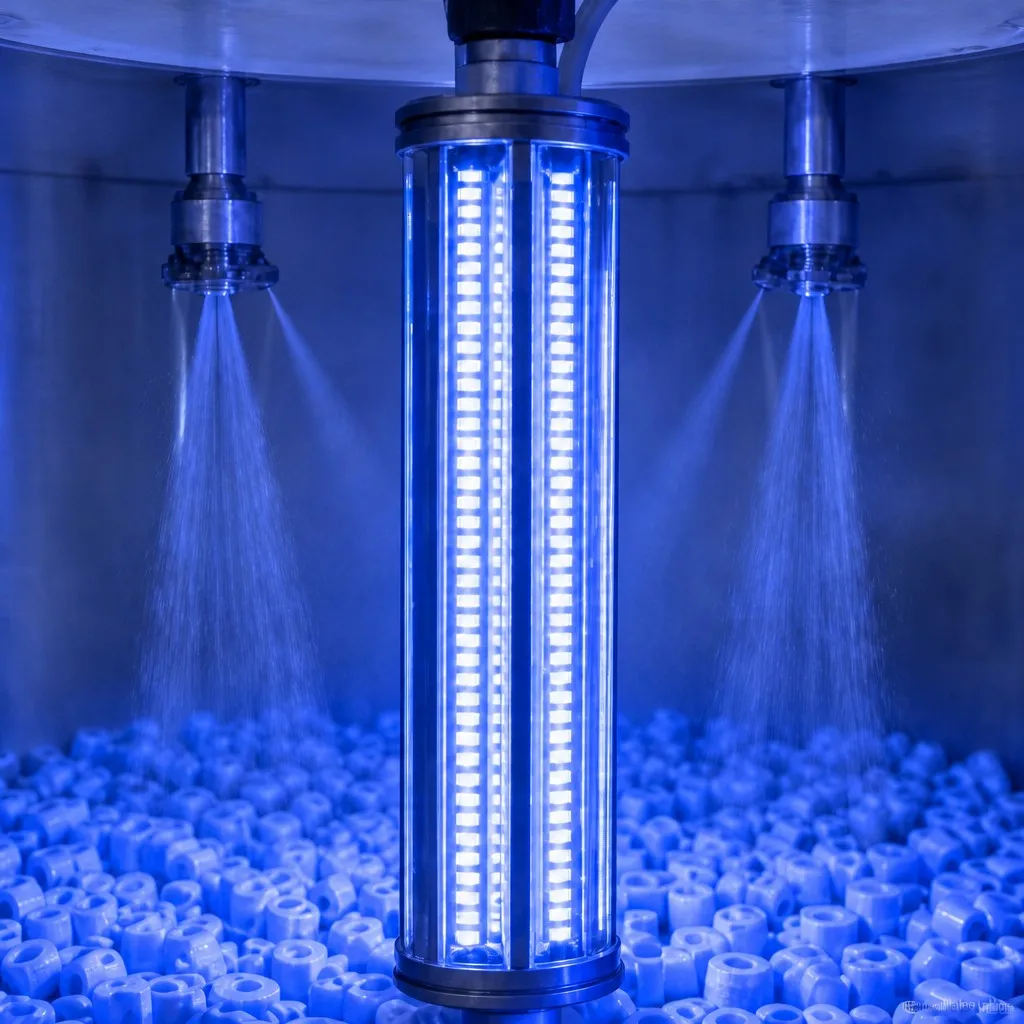
From Mercury to UV LED: 3 Technical Traps When Retrofitting Industrial Photocatalysis Systems
Trap 1: The Space-Fit Trap — Standard Modules Do Not Fit Non-Standard Ducts
What goes wrong
Photocatalysis towers and exhaust ducts are rarely built to a standard module grid. They are sized by airflow, by the physical footprint of the building, and by the position of existing fans, dampers, and access doors. A standard rectangular Uv Led Module looks clean in a catalogue and collides with reality on site. Three failure patterns recur:
- Length mismatch. A 1.2 m standard array cannot span a 1.45 m duct section without leaving an untreated shadow zone at one end — which is exactly where the contaminant escapes.
- Cross-section mismatch. Round ducts receive rectangular modules poorly; the corners of the module sit in the airflow shadow while the curved wall reflects light unpredictably.
- Structural conflict. Fan guards, dampers, and sensor probes occupy the space where a module "should" go. Forcing the module in blocks airflow or blocks access for maintenance.
The system-level answer: geometry is an integration input, not an afterthought
On a retrofit, the module geometry should be derived from the duct geometry, not the other way around. A supplier with in-house structure customization can produce length-matched arrays that fill the duct section end-to-end, curved or sectioned carriers that follow round or irregular cross-sections, and modular segments with service gaps that preserve airflow paths and leave access lanes for cleaning.
The engineering rule: the retrofit layout must be optimized for the airflow field, not for the module catalogue. When the array conforms to the duct, every cubic meter of treated air passes through the designed irradiance field, and dose uniformity becomes a designed property instead of a hope.
Trap 2: The Thermal-Balance Trap — Heat That Was Never a Problem Becomes the Whole Problem
What goes wrong
A mercury lamp radiates a large share of its input energy as heat and IR — the enclosure was designed around that. A UV LED module converts a higher share of input power into useful UV, but it concentrates the remaining heat in a small semiconductor junction (Tj). If the retrofit does not re-engineer the thermal path, the junction overheats, output decays, and the module fails early.
- UV LED output falls as junction temperature rises — typical sensitivity is on the order of 1–2% optical output reduction per 10 K junction rise (reference range; validate for your module).
- Sustained over-temperature accelerates lumen depreciation and shortens effective life well below the rated 50,000 hours of continuous operation (under rated operating conditions).
- In an enclosed duct retrofit, the module is effectively inside an oven — the surrounding airflow is hot, contaminated process air, not cooling air.
The system-level answer: design the heat path before the light path
| Cooling architecture | Typical fit | System notes |
|---|---|---|
| Passive (heat sink only) | Low power density, clean-air installs | Simplest; depends on ambient airflow around the module |
| Forced air (fan-cooled) | Medium power density | Requires a clean, filtered air supply — not process air |
| Water/glycol cooled | High power density, enclosed ducts | Independent of process air; stable Tj under load swings |
For retrofit projects, the deciding question is: can the module reject its heat into a medium that is NOT the process air? If the duct is sealed and the process air is hot or loaded with condensables, water-cooled or heat-exchanger-linked designs are usually the stable choice. Also plan for the transient: during a surge in contaminant load the LEDs are driven harder (see Trap 3), which raises dissipation exactly when you can least afford thermal drift. The thermal design must hold Tj within its rated window at the maximum drive condition, not at the average.
Trap 3: The Control-Logic Trap — The LED's Best Feature Is Useless Without the Right Controller
What goes wrong
The single biggest operational advantage of UV LED over mercury is instant, stepless output control. A mercury lamp must stay lit (or accept slow restrike times); an LED can be dimmed, pulsed, and sequenced in milliseconds. But if the retrofit merely wires the modules to a static power supply, that advantage is thrown away — and the operator pays for it in energy and lamp-hours.
Contaminant load is not constant. A food-processing exhaust line spikes at shift change; a paint shop spikes during coating runs. A fixed-output system must be oversized for the peak, which means it wastes energy and accelerates aging during the hours when the load is low.
The system-level answer: PWM control that follows the load
- Instant on/off (static). Acceptable for simple batch processes. Saves nothing during low-load hours.
- PWM (pulse-width modulation) dimming. The module output is modulated in proportion to the measured load signal (VOC sensor, airflow, or schedule). Output follows demand; energy and thermal load follow output.
The ROI case for PWM-controlled retrofits: energy scales with demand, so average consumption drops versus a fixed-output system sized for peak load (savings are application-specific — validate with your own load profile); running at reduced average drive current lowers junction temperature and slows depreciation, extending effective life toward the rated 50,000-hour envelope; and lower average dissipation means the cooling system is sized for the mean, not the peak.
The control interface matters too: a retrofit that cannot talk to the existing PLC/DCS (via 0–10 V, PWM input, or fieldbus) forces the operator into a second control system. Confirm the control interface as a contractual requirement, not a nice-to-have.
The Upgrade Decision Checklist: 5 Parameters to Confirm Before Retrofit
Before you commit to a mercury-to-UV LED retrofit, put these five numbers on paper. A supplier that asks for them is doing engineering; a supplier that does not is quoting lamps.
- Airflow (m³/h and velocity profile). What is the design airflow, and how uniform is the velocity across the duct cross-section? Dose delivered = irradiance × residence time; residence time comes from airflow and geometry. A high-velocity section needs a longer irradiation zone or higher irradiance to reach the same dose.
- Process temperature and humidity. What is the air temperature at the irradiation zone, and does it swing? Hot air raises module ambient temperature and shifts the thermal design. Humidity affects condensation on optical surfaces and — depending on the chemistry — photocatalytic efficiency.
- Physical space and access. What is the exact duct cross-section, available length, and access arrangement? Confirm flange types, access doors, and whether the array must be serviceable in place. This is the number that turns a "standard module" conversation into an engineering drawing.
- Required dose and target contaminants. What contaminant class are you treating, and what is the target removal performance? UV dose requirements vary by contaminant and catalyst system. Do not accept a "one-size-fits-all" irradiance spec — it should be derived from your target compound, your catalyst, and your residence time. (Typical reference ranges must be validated against your specific chemistry; never assume a fixed removal rate.)
- Control interface and power. Does the site have a PLC/DCS to link to? What signal standard (0–10 V, PWM, fieldbus)? What is the available electrical supply per zone? These decide whether you get load-following control — and the energy and life ROI that comes with it.
Why System-Level Retrofitting Matters: the Integration View
A retrofit is not a component purchase; it is a system re-engineering with three coupled domains — optics (space fit), thermal (heat balance), and control (load following). Neglect any one and the other two degrade: a poor space fit creates shadow zones, a poor heat path forces output derating, and a static control wastes the efficiency that justified the switch.
Tianhui UVLED approaches retrofits from this integration standpoint: geometry derived from the duct, thermal paths designed for the enclosure, and control interfaces built for the existing automation. The result is a system that behaves like it was designed for your plant — because it was.
Related reading: UV LED Curing: Why the Right Wavelength Matters More Than the Right Power — the wavelength-selection companion to this retrofit guide.
Frequently Asked Questions
Q1: Can I simply replace mercury lamps with UV LED modules in my existing photocatalysis tower?
You can — but a direct swap usually under-delivers. The enclosure, airflow, and control were designed around a mercury source. A proper retrofit re-engineers geometry, thermal path, and control. Treat it as a system change, not a lamp change.
Q2: How much does a UV LED retrofit typically save on energy?
There is no universal number. Savings depend on your load profile and whether the system uses load-following (PWM) control. Operators who move from fixed-output mercury to load-following LED typically see meaningful reductions, but the figure must be validated with your own operating data.
Q3: How long do UV LED modules typically last in a retrofit?
Under rated operating conditions, modules are typically rated for up to 50,000 hours of continuous operation. Output decays gradually over life, which directly reduces delivered dose over time — the ROI model should use the dose delivered across the life, not the initial dose. Validate the lifetime figure with your module supplier.
Q4: Do UV LED modules need water cooling in a duct retrofit?
Not always — it depends on power density and ambient conditions. If the duct is sealed and the process air is hot or condensable, water-cooled or heat-exchanger designs keep junction temperature stable. In clean, open, low-power installations, passive or forced-air cooling can suffice. The thermal design must be validated for your enclosure.
Q5: Will a PWM-controlled system actually extend module life?
Generally, yes: lower average drive current and lower junction temperature slow depreciation. The magnitude depends on your duty cycle and load swings. It is one of the strongest levers in a retrofit ROI model — but treat the life extension as an engineering estimate validated with your supplier.
Q6: How do I know if my duct geometry is compatible with a retrofit?
Measure the actual cross-section, available length, and access arrangements, then ask the supplier to provide a layout drawing derived from those measurements. If the supplier asks for your duct dimensions up front, that is a good sign; if they quote a standard module without asking, that is a warning.
Q7: Does Tianhui UVLED provide control-interface integration for existing PLC/DCS systems?
Tianhui UVLED supports control-interface integration for OEM and retrofit partners, including signal-standard matching for common automation systems. Confirm the specific interface options and compatibility for your project with our engineering team.
Conclusion
The three traps — space fit, thermal balance, control logic — are the difference between a retrofit that under-performs and one that delivers. Ask the five questions, design the system around your duct and your load, and the LED advantage becomes measurable: stable dose, controlled temperature, and energy that follows demand instead of running flat.